
Cross-hole IP/Resistivity Surveys for Gold & Voids
Cross-hole IP/Resistivity Surveys are carried out with C1-C2 transmitter current electrodes at ‘infinity’ perpendicular to the target strike and on each side of the target.
P1-P2 electrodes are placed in the borehole pairs and read in a semi-tomographic mode. A third electrode is typically positioned at one of the collars for quality control and to monitor the transmitter current as the surveys progresses.
Results are UBC3D inversion modeled using borehole survey data supplied by the client. ClearView’s in-house software is used to georeference the IP and resistivity data to the UBC3D input format so that results can be updated each day to optimize the next borehole pair to be surveyed.
Cross-hole Resistivity surveys can also be carried out for medium-scale geotechnical projects where voids are of interest. In the following image, a cross-hole resistivity survey was carried out with transmitter electrodes upstream and downstream along a canal and borehole pairs were logged from land boreholes to barge-drilled boreholes. The resulting 3d inversions indicated areas under the canal where potential voids were located.
A very small-scale cross-hole resistivity survey was carried out on a major Metrolinx project in the GTA (Toronto). Transmitter electrodes were located a few hundred metres on each side of the tightly spaced boreholes to check for potential voids next to piles.
The transmitter setup usually includes a complete on-site backup to ensure there is no down-time.
The wire used is new and after a few cross-hole projects, the borehole wire is transferred for surface work and new wire is used for borehole surveys to ensure there are no electrical leaks.
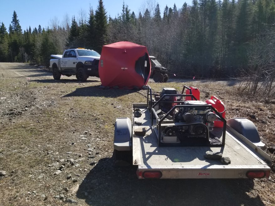
Cross-Hole IP Transmitter Setup

Operator preparing to be hoisted with crane to barge

Cross-Hole Resistivity from Barge for Voids under Canal
See also In Practice with a presentation at the bottom of this link.